OCEAN21 - Underwater ROV Vehicle Testing Asset (VTA)
August 2020 - June 2021
For my MechE Senior Design project, our team (OCEAN21) was tasked by our sponsors, Oceaneering International, Inc., to design an autonomous surface vehicle that can track and follow small underwater ROVs (remotely operated vehicle) during vehicle deployment testing.
To achieve this, our team designed, built, and tested a prototype vehicle testing asset (VTA) that is conveniently deployable, low cost, and can actively track and follow a tethered underwater vehicle in open water deployment environments. The VTA tracks and follows the ROV using both an autopilot system coupled with ROV vehicle state data stream, as well as a mechanical solution utilizing tether tension to estimate relative ROV positions.
The final Spring semester prototype outperformed a previous benchmark solution by 75%-90% in its performance metric (average tether tension reduction) under various operating conditions.
Our team was also awarded Best Presentation Award by a panel of ASME judges for our year end presentation.

Contributions
I was the team lead on this team project, and was responsible for the project's software control and electronic systems. My main contributions include:
- Design and implementation of the vehicle's controls, communications, power, and sensor systems
- Development of a communication protocol for transfer of vehicle state data
- Integration and deployment testing of subcomponents as well as the integrated system
- Project management and task delegation among the team
Skills used/learned
- Python, C++ object-oriented programming
- Sensors & filter algorithms (GPS, IMU, Strain gauges, Kalman Filter, etc.)
- Actuator & motor control
- Circuit design & power management
- Wired & wireless communication systems (Radio, TCP/IP, Serial, I2C, etc.)
- System integration & testing
- Project management, task delegation, internal & external communication
As motivation for the project, long range operations of ROVs commonly require long fiber cables for tele-operation and data transfer, since wireless connections are less than ideal underwater. A surface vehicle or floating device attached to the ROV with a shorter fixed length tether can serve as a wireless data relay and tether management system for the ROV. However, it can hinder the ROV's maneuverability, since the ROV has to drag the surface vehicle along with it.
By adding autonomous navigation capabilities to the surface vehicle, we can actively keep it within a certain threshold distance from the underwater ROV, to ensure that the connected tether is never taut, thus mitigating the tether tension that we are trying to reduce.
Small ROV vehicle testing is usually conducted in a medium-sized lake, which can have some mild wind and wave forces to consider (Sea-state 0), but our sponsors were also eager to potentially use the vehicle in more turbulent conditions in open seas.
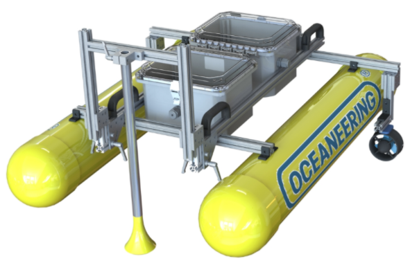
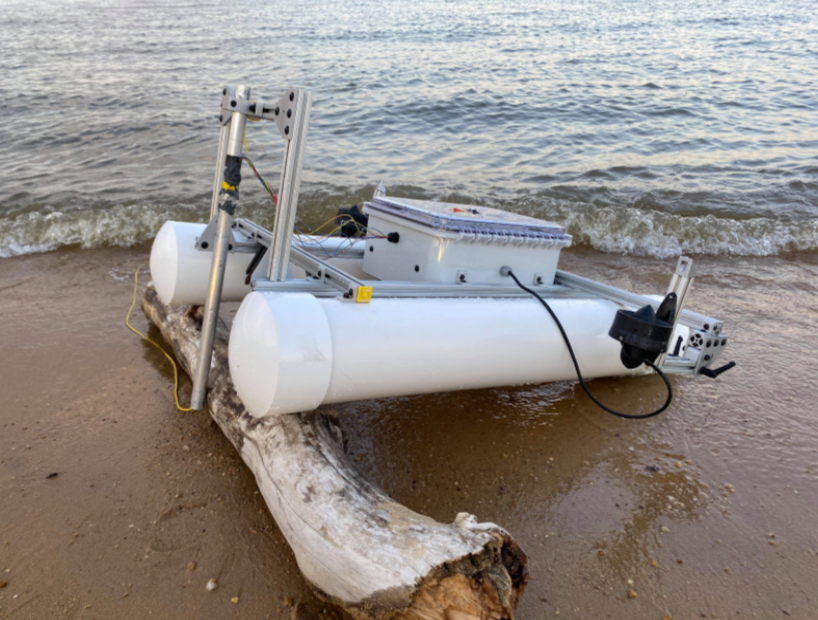
For the mechanical design, the vehicle is built from standard 80-20 T-slotted frames and PVC pipes for modularity during the prototyping process, measuring 40"x32"x20" and 45 lbs. The vehicle's underwater load-cell and thrusters are mounted on pivot structures to allow for compact storage and transportation.
The vehicle is powered with 2 underwater thrusters running at 20V, with battery capacity to enable 6 hour operations.
For the vehicle's control system, there are two main objectives: tracking of the ROV, and active navigation to follow.
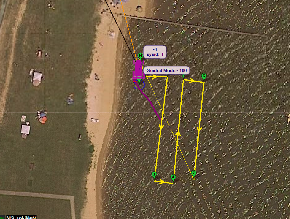
To track the ROV, the main approach is to establish a data-stream for the ROV's vehicle state from Oceaneering's separate ROV control system, including vehicle coordinates, depth, and speed. From there, waypoint commands can be given to the VTA for it to continuously predict the ROV's trajectory and follow the ROV, utilizing its own onboard GPS, IMU, compass, etc.
However, in rare scenarios in which data transfer fails, the VTA is equipped with an onboard custom load cell to measure tether tension and angle when it is taut. The VTA can then estimate the ROV's relative position and perform navigation. This system can operate independent from ground control commands, allowing it to operate in turbulent sea conditions that can interrupt wireless communication.
For the vehicle's navigation, high level commands such as waypoint are sent from the command station via radio. They are then processed and executed by a PixHawk 4 autopilot module installed with a modified ArduPilot autopilot software. Low level motor commands are then passed to an Arduino and then to motor controllers for actuation.